

Solar Rapid Shutdown Requirements: NEC 690.12 Guide For Installers

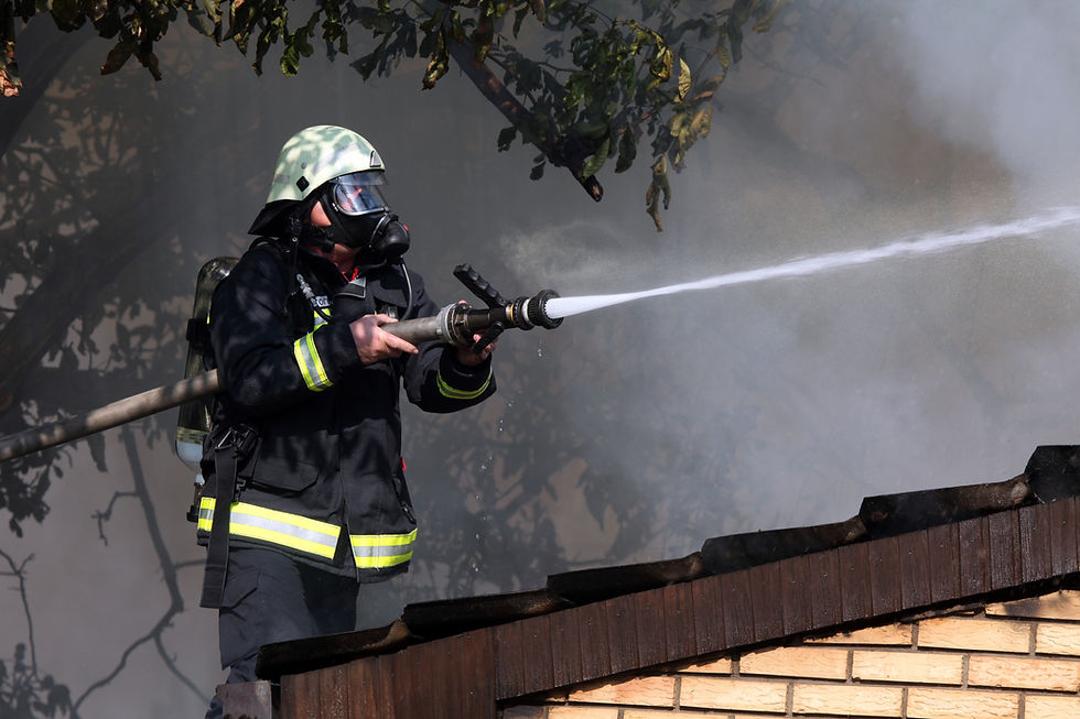
Every rooftop solar system has a problem that doesn't go away when the inverter shuts off. As long as the sun hits the array, the DC conductors running from your modules stay energized. A firefighter cutting into a roof during a structure fire has no way to know which conductors are live up there. That risk is exactly why solar rapid shutdown requirements exist under NFPA 70, Section 690.12.
NEC 690.12 rapid shutdown rules have changed with nearly every code cycle since 2014. If you're pulling permits across multiple jurisdictions, you're likely designing to more than one edition at the same time. This guide covers what NEC 690.12 requires today, the array boundary and voltage limits behind it, and the questions installers search for most: how a combiner box fits into a rapid shutdown design, what wire size an initiation device needs, and how the rules apply to commercial rooftop solar.
GreenLancer supports solar installers with permit-ready plan sets that include full rapid shutdown documentation built to AHJ requirements.
NEC 690.12 Rapid Shutdown At A Glance
Before the full breakdown, here's the short version installers actually need on a jobsite. Treat this as a starting point, not a substitute for checking your AHJ's adopted code year.
Question | Installer Answer |
Where does 690.12 apply? | PV circuits installed on or in buildings, with exceptions for certain ground mount and detached-structure installs |
Array boundary | 1 ft (305 mm) from the array in all directions |
Outside the array boundary | Controlled conductors reduced to 30V or less within 30 seconds |
Inside the array boundary | One method limits voltage to 80V or less within 30 seconds; a listed PVHCS may use a different UL 3741-evaluated method |
Initiation device | Service disconnect, PV system disconnect, or a listed switch, depending on the adopted NEC edition |
Ground mount systems | Not automatically exempt. Exception No. 1 covers circuits entering a building used solely to house PV equipment, and the 2023 NEC adds an exception for circuits terminating on a building's exterior |
Current NEC edition | The 2026 NEC is published and adopted in a growing number of states. Design to whatever edition your AHJ enforces |
What NEC 690.12 Requires
The core issue is simple. DC conductors between your modules and inverter stay live as long as there's sunlight. Firefighters performing vertical ventilation on a roof with an active array face real shock hazard from those conductors. Rapid shutdown gives them a way to de-energize the system before they're on the roof, and the requirement grew directly out of firefighter shock hazard research, including work referenced by UL Standards & Engagement.
NEC 690.12 applies to PV circuits installed on or in buildings. That phrase, "on or in buildings," is the key language driving most of the exceptions covered later in this guide. The rulemaking history includes direct input from fire service organizations and trade groups such as SEIA, which continues to track fire safety issues across the industry.
One thing worth clarifying for your crew: rapid shutdown protects first responders, not installers working on the system. It's a firefighter safety requirement, not a maintenance safety feature. Keep that distinction in mind when you're training techs on lockout procedures, since rapid shutdown and standard electrical safety practices aren't the same thing.
NEC 690.12 Array Boundary And Voltage Limits
Under NEC 690.12, the array boundary extends 1 ft from the PV array in all directions. Conductors outside the array boundary must generally be reduced to 30V or less within 30 seconds of rapid shutdown initiation. Inside the array boundary, one compliance method limits voltage to 80V or less within 30 seconds.
The array boundary term didn't always exist. The 2014 NEC controlled conductors based on distance from the array (more than 5 ft inside a building or more than 10 ft from the array) rather than a defined boundary line. The 2017 NEC introduced the 1 ft array boundary and split conductors into two zones: inside the boundary and outside it, each with its own voltage limit.
This distinction matters at plan review because it's the spec reviewers check first on the one-line. If your design shows a single voltage limit for the whole DC system instead of separating inside-boundary and outside-boundary conductors, expect a correction. It's also the source of most of the exam-style search queries you'll see referencing "array boundary" and specific inch or voltage figures.
Array boundary: 1 ft (305 mm) from the array perimeter, in all directions
Outside the boundary, but within the building: 30V or less within 30 seconds
Inside the boundary, voltage-limitation method: 80V or less within 30 seconds
A listed PVHCS may achieve equivalent protection through a different, equipment-specific method evaluated under UL 3741 rather than the flat 80V limit
Rapid Shutdown Compliance Methods: MLPE And PV Hazard Control Systems
This is the decision you're making on every job. NEC 690.12(B)(2) provides more than one way to control shock hazard inside the array boundary, and installers commonly group the options into module-level power electronics (MLPE) and PV hazard control systems (PVHCS). Both can be used to satisfy NEC 690.12 when the equipment and installation meet the applicable listing and code requirements, but they carry very different implications for design, cost, and plan review.
Module-Level Power Electronics
MLPE covers two configurations most installers already know. Microinverters like the Enphase IQ series convert DC to AC at the module. When you cut AC power, the system de-energizes and there are no high-voltage DC conductors running to a central inverter.
Power optimizers paired with string inverters work differently. When the initiating device opens, the inverter signals the optimizers to throttle module voltage down to safe levels within 30 seconds. The optimizer and inverter must be tested and certified together as a rapid shutdown system, so mixing brands or substituting components mid-job breaks the listing. That can create a plan-review or inspection issue.
MLPE is the most AHJ-familiar approach, and most plan reviewers have seen it dozens of times. The tradeoff is more electronic components on the roof, more connection points, and more potential failure modes over the life of the system.
UL 3741 PV Hazard Control Systems
UL 3741 evaluates the entire array as a system, including modules, racking, and wiring. A listed PVHCS can provide the required shock-hazard control without module-level shutdown electronics, in configurations covered by the listing. Several racking manufacturers now offer UL 3741-listed systems compatible with major string inverters, opening the door to compliant string-only designs on larger commercial jobs where microinverters don't scale well.
The catch is component matching. Every element has to be part of the same listed system, so swapping in a different racking product or a different inverter than what's in the listing breaks compliance. AHJ familiarity with PVHCS is also lower than with MLPE, based on recent field reporting from Mayfield Renewables. Plan to include more documentation in your submittal if you're going this route.
When Each Approach Makes Sense
MLPE tends to be the default for residential and most standard commercial jobs, mainly because plan reviewers already know what they're looking at. PVHCS earns its keep on larger commercial roofs and string-inverter designs where reducing component count and connection points outweighs the extra documentation.
If you're going the string-inverter route, our solar string sizing calculator checks temperature-corrected string voltage and current against inverter input limits before you submit.
MLPE | PVHCS (UL 3741) | |
Roof components | Optimizer or microinverter at each module | Modules, racking, wiring only |
AHJ familiarity | High | Growing but inconsistent |
Component flexibility | Moderate, must match certified system | Low, full system listing required |
Best for | Residential, most commercial jobs | Larger commercial, string-inverter designs |
Plan review documentation | Standard | More detailed listing documentation needed |
Rapid Shutdown Initiation Devices: Location, Wiring, And Wire Size
NEC 690.12 does not specify one universal wire size for every rapid shutdown initiation device. The correct conductor size and wiring method depend on the listed equipment, the manufacturer's installation instructions, whether the initiation signal is line voltage or a control circuit, and the applicable overcurrent protection and terminal ratings.
That's a more accurate answer than a single AWG figure, and it's also where most of the confusion on this topic comes from. Installers searching for a fixed wire size are usually trying to shortcut a step that genuinely varies by equipment.
Location Requirements For One- And Two-Family Dwellings
Must be at a readily accessible location outside the building
Standard practice is at the service entrance or utility meter on the exterior wall
Readily accessible means no locks, no ladders, no tools required
Follow the adopted NEC edition and the listed equipment's installation instructions for exact placement
Show the location clearly on the site plan and one-line diagram
Check The Manufacturer's Wiring Instructions First
Every listed rapid shutdown component ships with installation instructions that specify conductor requirements for its initiation circuit. That's your starting point, not a generic NEC table.
For example, Enphase's System Shutdown Switch technical brief specifies 12 AWG wire for the connection to the IQ System Controller. If you use a knife blade disconnect instead, Enphase allows 14 to 6 AWG copper spliced to the provided 12 AWG wire. Neither figure is a universal rapid shutdown wire size, so follow the instructions for your specific listed equipment and configuration.
For SolarEdge systems, the inverter AC disconnect or the service disconnect can serve as the RSD initiator, but this must be explicitly documented on the plan set.
Line-Voltage Vs. Control-Circuit Initiation
Some rapid shutdown systems send initiation signals over a line-voltage circuit, while others use a low-voltage control circuit or a communication path like power line carrier. The wiring method, conductor insulation, and ampacity requirements differ between the two. Confirm which type your equipment uses before you spec conductors.
Conductor Ampacity, OCPD, And Terminal Ratings
Once you know the circuit type, size the conductor to the actual load, the equipment's terminal ratings, and the required overcurrent protection for that circuit. Undersized conductors on an initiation circuit create voltage drop and unreliable rapid shutdown performance, which is a safety issue on top of a compliance one.
Show Initiation Wiring On The Plan Set
Reviewers want to see the initiation device, its wiring method, and its relationship to the array boundary clearly on the drawings. A clean solar one-line diagram that matches your equipment documentation avoids one of the most common RSD corrections.
Quick check before you submit:
☐ Manufacturer's RSD wiring instructions pulled and referenced
☐ Initiation circuit type confirmed (line voltage vs. control circuit)
☐ Conductor ampacity and OCPD verified against the equipment listing
☐ Initiation device and wiring shown on the one-line diagram
☐ Multiple inverter or RSD zones coordinated with a single initiating device where required

NEC 2020 Rapid Shutdown Combiner Box Requirements
NEC 690.12 does not require every rapid shutdown system to use a special rapid shutdown combiner box. Whether a combiner is part of the rapid shutdown architecture depends on the selected equipment and its listing. In a listed PV hazard control system, combiners, conductors, inverters, and other components may be evaluated together as part of the listed system.
This is worth stating plainly because the query behind this section suggests installers are looking for a combiner-specific rule that doesn't actually exist as its own code section. The real answer lives in how your chosen compliance method treats the combiner, not in a separate combiner mandate.
When A Combiner Box Is Part Of The Rapid Shutdown System
A PVHCS listing can include the combiner, its wiring, and its connection to the inverter as part of the evaluated system, similar to how IAEI Magazine describes PVHCS components including modules, wiring, harnesses, racking, combiners, disconnects, actuators, and inverters. If your job uses MLPE instead, the combiner is typically just a standard string combiner outside the rapid shutdown listing itself, and the RSD function lives at the module or optimizer level.
Combiner Location And The Array Boundary
Combiner location matters because it affects the routing and classification of PV conductors relative to the array boundary. Conductors outside the array boundary generally must meet the outside-boundary rapid shutdown limits, while circuits within the array boundary must satisfy one of the permitted inside-boundary shock-hazard-control methods. For a PVHCS, confirm that the combiner, conductor routing, and other equipment match the listed system configuration before you finalize the site plan.
What Belongs On The One-Line Vs. The Site Plan
Keep the electrical function and the physical placement separate on your drawings. The one-line diagram should show the combiner's electrical role: string inputs, output circuits, and its relationship to the rapid shutdown equipment and initiation method. The site plan should show its physical location relative to the array boundary, the inverter, and the initiating device. Our solar plan sets guide covers how these documents work together across a full submittal.
Get a permit-ready plan set with combiner box, initiation device, and array boundary documentation built to your AHJ's code year.
How NEC 690.12 Applies To Commercial Rooftop Solar
NEC 690.12 generally applies to commercial rooftop PV because the array is installed on a building. The same controlled-conductor and array-boundary requirements apply, but commercial systems often involve more strings, combiners, inverters, and rooftop conductor routing. That complexity can make the rapid shutdown architecture and plan-set documentation more involved than a typical residential job.
Multiple Arrays, Inverters, And Initiation Zones
Commercial jobs commonly involve multiple rooftop arrays, separate inverter groups, more than one combiner, and in some cases more than one shutdown zone. Where multiple PV systems are installed on a single service, the code sets limits on how many initiation devices or switches can be grouped and how they must coordinate to shut down every connected system together.
Whether MLPE or PVHCS makes more sense on a given commercial roof depends heavily on the specific equipment and roof geometry, not a blanket rule. Manufacturers like Fronius publish guidance on weighing MLPE against UL 3741-based compliance for larger string-inverter systems, which is worth reviewing before you lock in a design approach. For a full walkthrough of what a commercial submittal needs beyond RSD, see our commercial solar permit design guide.
Does Rapid Shutdown Apply To Ground-Mounted Solar?
Ground-mounted solar doesn't automatically require rapid shutdown, but it isn't automatically exempt either. NEC 690.12 governs PV system circuits installed on or in buildings, so a freestanding ground-mounted array doesn't trigger rapid shutdown by itself. The answer depends on where the array's circuits go once they reach a building and which NEC edition your AHJ enforces.
Two exceptions matter most for ground mounts. Exception No. 1 to 690.12, in place since the 2017 NEC, covers ground-mounted circuits entering a building whose sole purpose is to house PV system equipment. The 2023 NEC added a second exception in 690.12(A) for circuits from arrays not attached to buildings that terminate on a building's exterior.
Exception No. 1 Depends On The Building, Not The Array
Running DC conductors from a ground mount into a house to reach an indoor inverter doesn't qualify for Exception No. 1, even when those conductors serve only the PV system. A home serves purposes beyond housing PV equipment, so the exception doesn't apply.
A dedicated inverter shed or equipment enclosure is different. If the structure's sole purpose is housing PV equipment, DC circuits can enter it without rapid shutdown. Note the exception in your plan set so the reviewer doesn't have to guess.
The 2023 NEC Exterior Termination Exception
Under the 2023 NEC and later, a ground mount can route DC circuits to an inverter mounted on the outside of a building without treating those circuits as controlled conductors. The same exception covers PV circuits installed in accordance with 230.6, which defines when conductors are considered outside a building.
The exception has limits. Conductors that continue inside the building, such as a DC run from an exterior disconnect to an indoor inverter, can still be controlled conductors. Some AHJs on the 2020 NEC accept the 2023 language as a clarification, but confirm that before relying on it.
Rapid Shutdown By Ground-Mount Configuration
Most ground-mount rapid shutdown questions come down to inverter location, conductor routing, and code edition. Use this table as a starting point, then confirm the AHJ's interpretation.
Ground-Mount Configuration | Rapid Shutdown Implication |
Inverters at the array, with only AC output circuits running to the building | No PV DC circuits reach the building. Evaluate any inverter output circuit requirements under the adopted NEC edition and the listed system configuration |
DC circuits run to a detached building whose sole purpose is housing PV equipment | Exception No. 1 generally applies. Document the building's use and the exception in the plan notes |
DC circuits terminate at an inverter or other equipment on a building's exterior | Under the 2023 NEC and later, the 690.12(A) exception generally applies. Under earlier editions, verify the AHJ's interpretation before leaving out rapid shutdown |
DC circuits run inside a home or other building not used solely for PV equipment | Neither exception covers the conductors inside the building. They're generally controlled conductors limited to 30V within 30 seconds under 690.12(B)(1), and initiation device and labeling rules still apply |
Check the adopted NEC edition before deciding that a ground-mount circuit needs rapid shutdown just because it reaches a building.
What To Document For A Ground-Mount Submittal
Reviewers want to see why rapid shutdown does or doesn't apply. Show the inverter location, DC and AC conductor routing to each building, and the adopted NEC edition. If you're relying on an exception, cite it in the plan notes.
Long DC runs from a ground mount to the building also need conductor sizing documented. Our NEC 690.8 calculator finds the minimum conductor ampacity for PV circuits before you finalize the one-line.
Confirm your approach with the AHJ, since earlier NEC language was ambiguous and some inspectors still apply older interpretations in the field. Our ground mount solar permit requirements guide covers the rest of what a freestanding array submittal needs.
Carports, Canopies, And Detached-Structure Exceptions
The 2023 NEC added an explicit exception for PV equipment and circuits on non-enclosed detached structures, including carports, solar trellises, and parking shade structures. The exception reflects the lower likelihood of the rooftop firefighting operations that drove the original rapid shutdown requirement on enclosed buildings.
This exception only exists in jurisdictions that have adopted the 2023 NEC or later. If your AHJ is still enforcing the 2020 NEC, the exception doesn't exist yet and you need to design accordingly. Conductors running from a carport into the main building matter too. If those conductors enter the building through the exterior and remain on the exterior per NEC 230.6, they generally aren't treated as controlled conductors. If they penetrate into the building, rapid shutdown applies to that portion of the circuit.
Detached garages sit in a gray area. An enclosed detached garage does not fit the non-enclosed-structure exception simply because it's detached from the main building. Evaluate the installation under the adopted version of NEC 690.12 and confirm the AHJ's interpretation before claiming an exception.

Rapid Shutdown Labeling Under NEC 690.12(D)
As of the 2023 NEC, RSD marking requirements moved from Section 690.56(C) into Section 690.12(D). If your jurisdiction is still on the 2020 NEC, marking requirements remain in 690.56(C). Referencing the wrong section on your plan set is a fast way to draw a correction even when the design itself is solid.
NEC 690.12(D) actually covers two distinct labels, and mixing them up is a common source of confusion on plan sets.
Building Rapid Shutdown Placard
This is the label first responders see first. It must be located at each service equipment location the PV system connects to, or at an approved readily visible location that identifies where the initiation devices are. Under the 2023 NEC, it must include a simple diagram of a building with a roof and the following wording:
SOLAR PV SYSTEM IS EQUIPPED WITH RAPID SHUTDOWN. TURN RAPID SHUTDOWN SWITCH TO THE "OFF" POSITION TO SHUT DOWN PV SYSTEM AND REDUCE SHOCK HAZARD IN ARRAY.
The 2023 NEC removed the specific color and reflectivity requirement for this placard. Text only needs to contrast the background
Buildings with more than one rapid shutdown type, or with a PV system that has no rapid shutdown, need a detailed roof plan diagram showing each PV system, with a dotted line around areas that remain energized after shutdown. This rule moved from 690.56(C)(1) to 690.12(D)(1) in the 2023 NEC

Rapid Shutdown Switch Label
This is the second, separate label. It goes on or within 1 meter (3 ft) of the rapid shutdown switch itself and confirms the responder found the right device. The wording and format have stayed consistent across recent editions:
RAPID SHUTDOWN SWITCH FOR SOLAR PV SYSTEM
Reflective, white lettering on a red background
Letters capitalized, minimum height 3/8 in (9.5 mm)
NEC 110.21 requires field-applied labels to be durable and suitable for the environment. Paper and standard laser-print labels fail on exterior equipment
For the full label package required on a solar permit, see our solar labeling requirements guide, which covers the complete label schedule including service equipment directories, disconnect labels, and ESS warning labels for storage jobs.
NEC Rapid Shutdown Changes: 2014 Through 2026
Here's what changed and when, so you can spot which cycle your AHJ is enforcing without digging through the full code text. Don't spend too much time on the early cycles if your market has moved on, but you should know what your AHJs are checking against.
2014 NEC: Rapid Shutdown Is Introduced
Rapid shutdown entered the code for the first time. Conductors extending more than 5 ft inside a building or more than 10 ft from the array had to be reduced to 30V and 240 volt-amperes within 30 seconds of initiation, following a later amendment. There was no defined array boundary yet, and no rule on where the initiation device had to be located.
2017 NEC Rapid Shutdown: Array Boundary And Module-Level Control
This was the update that fundamentally changed job design for most residential installers, according to IAEI Magazine. The array boundary was defined at 1 ft, and one compliance path required conductors inside the boundary to be limited to 80V within 30 seconds. The code also added Section 690.12(C), requiring a marked initiation device outside the building for one- and two-family dwellings.
The inside-boundary requirement in 690.12(B)(2) had a delayed effective date of January 1, 2019. The delay gave manufacturers time to bring compliant equipment to market.
The 2014 NEC controlled conductors leaving the array, which installers often call array-level rapid shutdown. The 2017 NEC added voltage control inside the array boundary, commonly called module-level rapid shutdown because MLPE became the main way to comply.
The code doesn't mandate a device on every module. The 2020 NEC then recognized listed PV hazard control systems (PVHCS) as another compliance path.
2020 NEC Rapid Shutdown: UL 3741 And PVHCS Enter The Code
The 80V/30-second rule stayed in place, but the 2020 NEC added the PVHCS pathway under UL 3741 as a listed alternative to MLPE inside the array boundary. This opened the door to compliant string-only designs without module-level hardware, provided every component was part of the same listed system.
2023 NEC: Exceptions And Clarifications Expand
The 2023 cycle added the carport and non-enclosed detached structure exceptions covered earlier in this guide, along with a 690.12(A) exception for circuits from arrays not attached to buildings that terminate on a building's exterior. Marking requirements also moved from 690.56(C) to 690.12(D), consolidating labeling provisions in one place.
2026 NEC: Initiation Device Requirements Are Reorganized
The most significant revision in the 2026 NEC is in Section 690.12(C). The initiation device requirements were reorganized into clearer subdivisions covering type and location, operation, and rules for multiple PV systems, aligning the section with the NEC Style Manual's format. The list of permissible initiation devices was simplified to a service disconnecting means, a PV system disconnecting means, or a listed switch. The prior wording requiring a switch to plainly indicate an "off" or "on" position was also removed, giving listed switch designs, including emergency-stop (E-stop) style switches, more flexibility under the 2026 language.
NEC Edition | Major Rapid Shutdown Change |
2014 | Introduced rapid shutdown |
2017 | Established the 1 ft array boundary and inside-boundary voltage control |
2020 | Added PVHCS as a listed compliance pathway |
2023 | Added detached-structure exceptions and reorganized marking provisions |
2026 | Reorganized initiation-device requirements and clarified equipment and location language |
A growing number of states have already moved to the 2026 NEC, while others remain on 2023 or 2020. Design to the edition your AHJ enforces, not automatically to the newest published edition. The NEC enforcement map is a good starting point, but always confirm directly with the local AHJ before finalizing a design.
What Your Solar Plan Set Needs For RSD
AHJs look at a few specific items when reviewing rapid shutdown documentation. Missing any of them is a predictable correction that delays approval.
What needs to be on the one-line:
RSD compliance method identified (MLPE type or PVHCS listing)
Initiating device shown with location
Rapid shutdown system components labeled with listing information
What needs to be on the site plan:
Initiating device location relative to service equipment
Array layout if a roof plan is required by the local checklist
If claiming a carport or ground-mount exception, the structure type and exception basis noted in the plan notes
Equipment documentation to include:
UL listing confirmation for the rapid shutdown system (MLPE certification or PVHCS listing documentation)
Equipment data sheets showing the specific model numbers included in the certified system
Getting the solar permit package right means all three documents tell the same story. A one-line showing SolarEdge optimizers paired with an inverter that isn't tested with them, or a plan note claiming the 2023 NEC carport exception in a 2020 NEC jurisdiction, is likely to trigger a correction.
GreenLancer's solar plan sets can include the rapid shutdown method, one-line details, initiation device location, equipment specifications, and applicable labeling required for AHJ review.
What Information To Gather Before Ordering A Plan Set
The sections above cover what a designer needs to show on your drawings. Before you order a plan set, it helps to have this information ready so the rapid shutdown design comes back right the first time.
AHJ and the NEC edition it currently enforces
Inverter make and model
MLPE or RSD equipment make and model
Module and racking system
Proposed combiner and inverter locations
Whether the project is rooftop, carport, or ground mount
Common RSD Mistakes That Get Plans Kicked Back
Most rapid shutdown corrections come from a short list of repeat issues. Check these before you hit submit.
Specifying an inverter as "RSD-capable" without confirming full system certification
Mixing optimizer brands with an inverter not included in the same certified system
Claiming the 2023 NEC carport exception in a jurisdiction still on the 2020 NEC
Showing the initiating device inside the building on the one-line for a residential job
Referencing 690.56(C) in a 2023 or 2026 NEC jurisdiction, where that section no longer covers RSD marking
Sizing initiation device conductors without checking the manufacturer's listing instructions
Assuming a combiner box needs special RSD-specific wiring when it's outside the listed system
No roof plan when the local AHJ checklist requires one
Late equipment substitution that changes the RSD compliance method without updating the plan set and label notes
Pre-Submittal Rapid Shutdown Checklist
☐ Confirmed which NEC cycle the AHJ has adopted
☐ Compliance method identified (MLPE or PVHCS) and documented on the one-line
☐ Initiating device location and wiring shown on site plan and one-line
☐ Conductor size for the initiation circuit verified against manufacturer instructions
☐ Combiner box role in the RSD system clarified, whether part of a PVHCS listing or standard equipment
☐ Placard wording and placement per 690.12(D), or 690.56(C) if the jurisdiction is on the 2020 NEC
☐ Equipment data sheets included confirming RSD system listing
☐ If a carport or ground-mount exception applies, basis documented in plan notes and code year confirmed
☐ Label materials specified as durable and suitable for exterior use per NEC 110.21

Partner With GreenLancer for Permit Ready Plan Sets
GreenLancer helps solar contractors prepare permit-ready residential and commercial PV plan sets for AHJ review. Our solar design and engineering network documents NEC 690.12 rapid shutdown requirements, including array boundaries, MLPE or PVHCS equipment, initiation devices, conductor routing, one-line diagrams, equipment callouts, and required rapid shutdown labels.
FAQ: Solar Rapid Shutdown Requirements And NEC 690.12
What Is Rapid Shutdown For Solar?
Rapid shutdown is a firefighter safety requirement under NEC 690.12 that requires PV systems installed on or in buildings to de-energize DC conductors to safe voltage levels within 30 seconds of initiation. The rule exists because DC conductors between your modules and inverter stay live as long as the sun is shining, even after the inverter is off.
What Does NEC 690.12 Require?
NEC 690.12 requires PV circuits installed on or in buildings to include a rapid shutdown function. Conductors outside the array boundary must drop to 30V or less within 30 seconds, and conductors inside the boundary must drop to 80V or less within 30 seconds under the voltage-limitation method, or use an equivalent listed PVHCS approach.
What Is The NEC 690.12 Array Boundary?
The array boundary is defined as 1 ft (305 mm) from the PV array in all directions. It was introduced in the 2017 NEC and determines which voltage limit applies to a given conductor, 30V outside the boundary or 80V inside it under the standard voltage-limitation method.
When Did Module-Level Rapid Shutdown Become Required?
The 2017 NEC added voltage control inside the array boundary, commonly called module-level rapid shutdown. That requirement in 690.12(B)(2) took effect January 1, 2019. Enforcement in a given area depends on when the state or AHJ adopted the 2017 NEC or a later edition.
Does Rapid Shutdown Apply To Ground-Mounted Solar Systems?
Not always, and the answer depends on the NEC edition. Exception No. 1 covers ground-mounted circuits entering a building whose sole purpose is housing PV equipment, and the 2023 NEC exempts circuits from detached arrays that terminate on a building's exterior. For circuits that run inside a home or other building, the applicable rapid shutdown requirements must be evaluated for the conductors on or in that building.
Are Solar Carports Subject To Rapid Shutdown?
Under the 2023 NEC and later, non-enclosed detached structures including carports, solar trellises, and parking shade structures are explicitly exempt. This exemption only applies in jurisdictions that have adopted the 2023 NEC or later.
What Is The Difference Between MLPE And A PV Hazard Control System?
MLPE achieves compliance at the module level using optimizers or microinverters. A PVHCS under UL 3741 achieves compliance at the system level, evaluating the full array, including racking and wiring, as a listed unit. Both can satisfy NEC 690.12 when properly listed and installed.
Does NEC Specify A Wire Size For A Rapid Shutdown Initiation Device?
No universal conductor size is specified by 690.12 itself. The correct wire size depends on the listed equipment's manufacturer instructions, whether the initiation circuit is line voltage or control voltage, and the applicable overcurrent protection and terminal ratings. For example, Enphase specifies 12 AWG wire for its System Shutdown Switch connection to the IQ System Controller, but that applies only to that listed equipment.
Does NEC 2020 Require A Rapid Shutdown Combiner Box?
No. NEC 690.12 doesn't create a separate rapid shutdown combiner box requirement. Whether a combiner is part of the rapid shutdown system depends on the compliance method chosen. In a listed PVHCS, the combiner may be included in the system evaluation.
What Does The Rapid Shutdown Label Need To Say?
NEC 690.12(D) requires two separate labels. The building placard reads "SOLAR PV SYSTEM IS EQUIPPED WITH RAPID SHUTDOWN" with operating instructions and a building diagram, located at the service equipment. The switch label reads "RAPID SHUTDOWN SWITCH FOR SOLAR PV SYSTEM" and goes within 1 meter (3 ft) of the switch itself.
Does Rapid Shutdown Apply To Commercial Rooftop Solar?
Yes. NEC 690.12 applies to commercial rooftop PV the same way it applies to residential systems, since the array is installed on a building. Commercial jobs often involve more strings, combiners, inverters, and initiation zones, which can make the documentation more involved.
Do All Solar Inverters Have Rapid Shutdown?
No. An inverter being listed for solar use doesn't automatically mean the full PV system complies with NEC 690.12. Rapid shutdown compliance depends on the inverter, the RSD or MLPE equipment, the system configuration, the applicable listings, and the NEC edition adopted by the AHJ.



Comments